Model H: IBM Keyboard USB Conversion
The IBM Model M keyboard has a cult following. It’s heavy, about two kilograms thanks to the steel backplate, and loud thanks to the buckling springs. They’ve been manufactured from 1984 until present day (now by Unicomp).
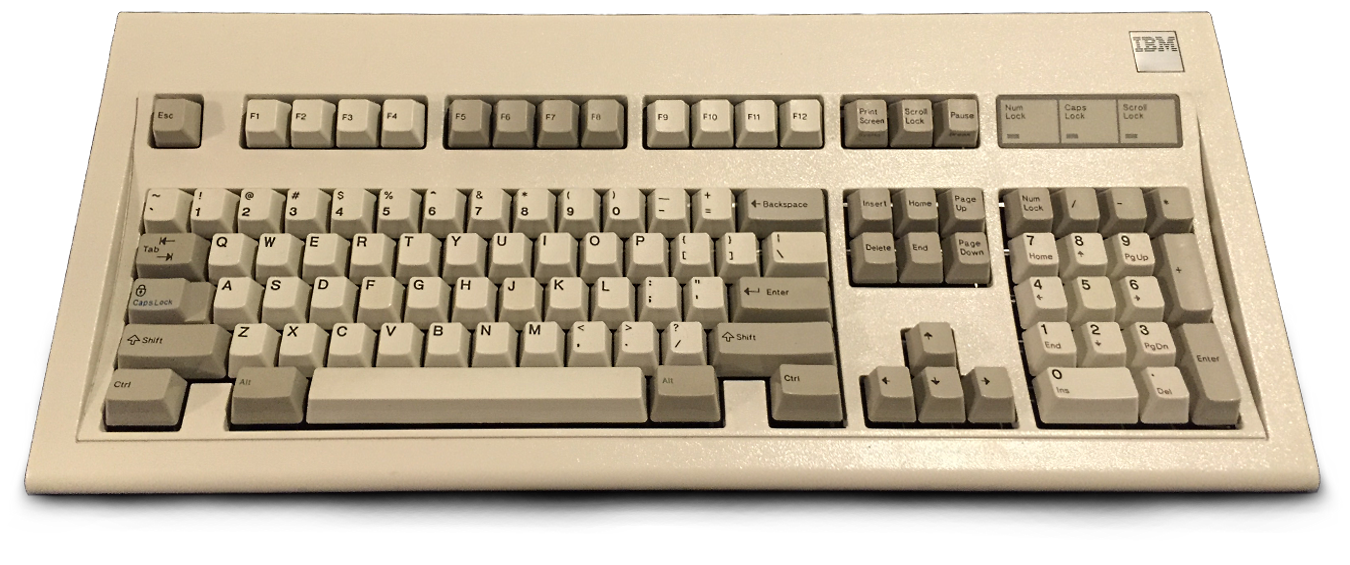
I’d always been curious about these keyboards so I bought one off ebay a few years ago. The feel of typing on it really lives up to it’s reputation. You can hear the springs ping and reverberate after each keypress (whether this is good is probably subjective).
There’s some downsides to this keyboard, of course: it has no windows/super key, no N-key roll-over, but perhaps most obvious today is the lack of USB. Model M’s, at least of the IBM era mine comes from, either have a hardwired PS/2 connector, or a removable SDL connector which adapts to either PS/2 or to a 5-pin DIN AT.
There are adapters from PS/2 to USB, but only some work with the Model M. Most PS/2 to USB adapters are passive, they don’t actually convert between the protocols but are designed for newer PS/2 keyboards which know about USB. For the Model M an active USB adapter is needed. Then even on some of those, the Model M uses too much power for a USB 1.0 device, which can cause issues. There of course do exist adapters which do work, one of the more powerful being “Soarer’s Converter”.
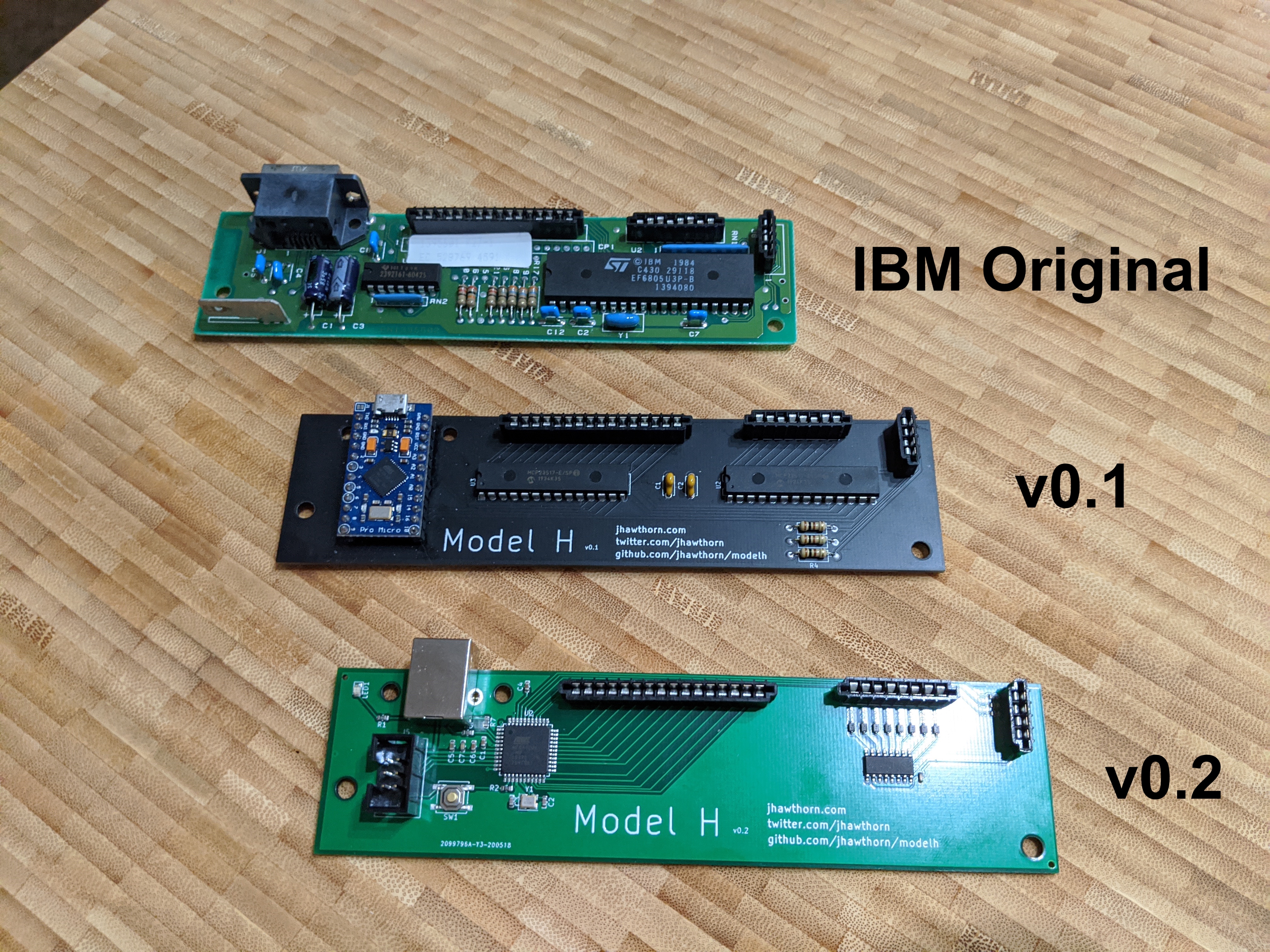
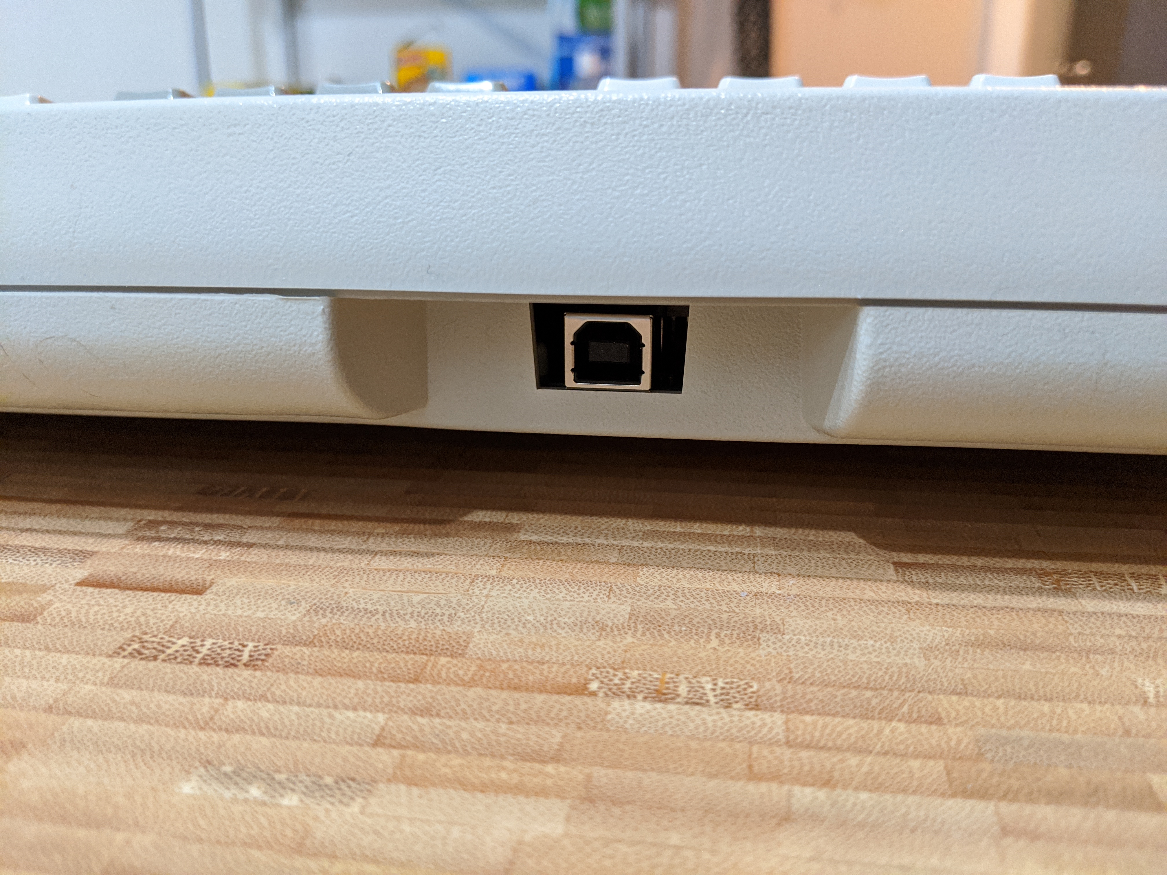
I wanted to take a different approach. Instead of using an adapter for the original controller, I wanted to replace it with a modern, QMK firmware-based controller. To do this I designed and manufactured a custom PCB, sourced parts for it, and eventually had it machine assembled. This allows no adapters, just a single USB cable between my computer and the keyboard, and as much control as possible over the keyboard.
Connectors
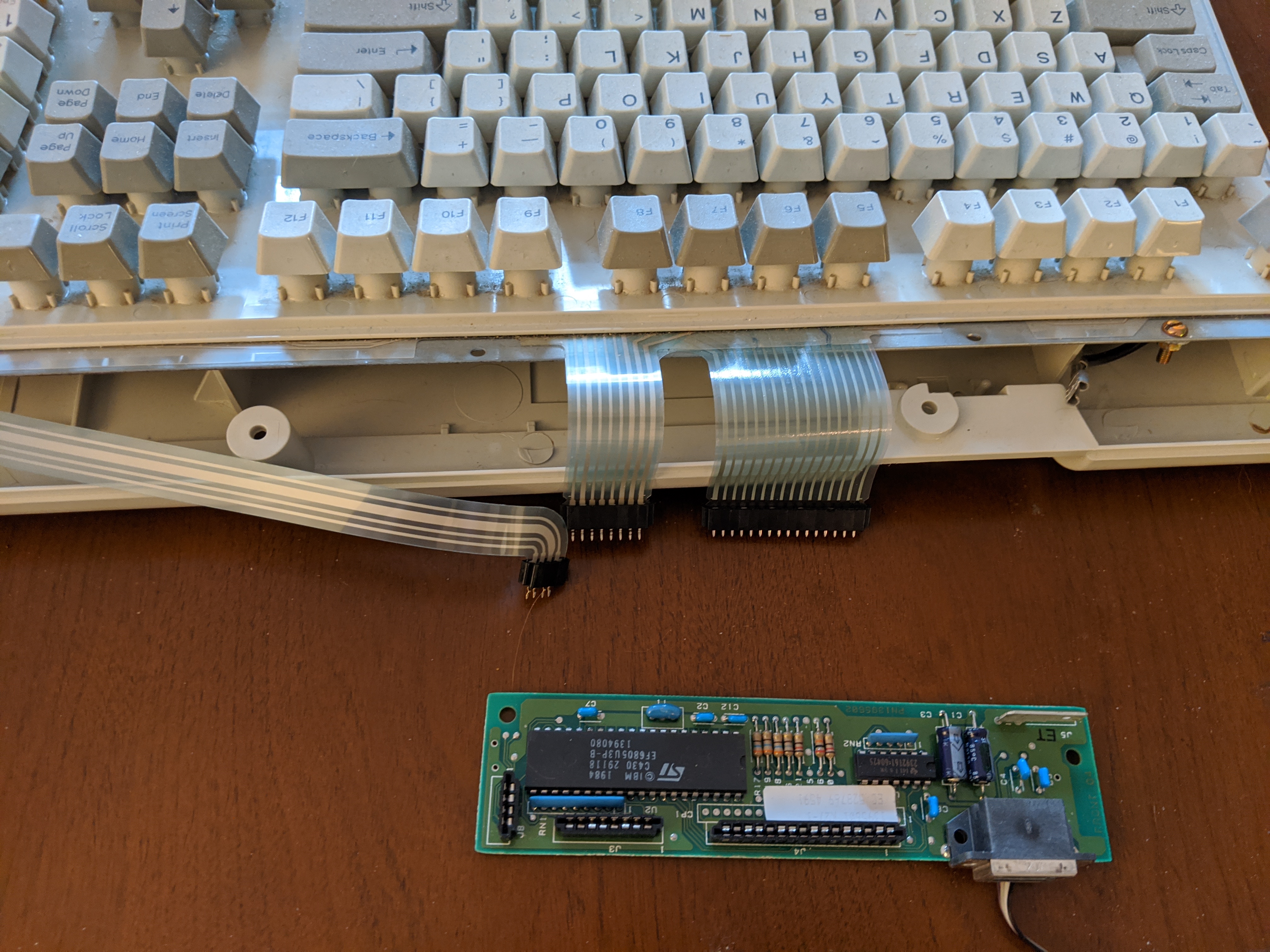
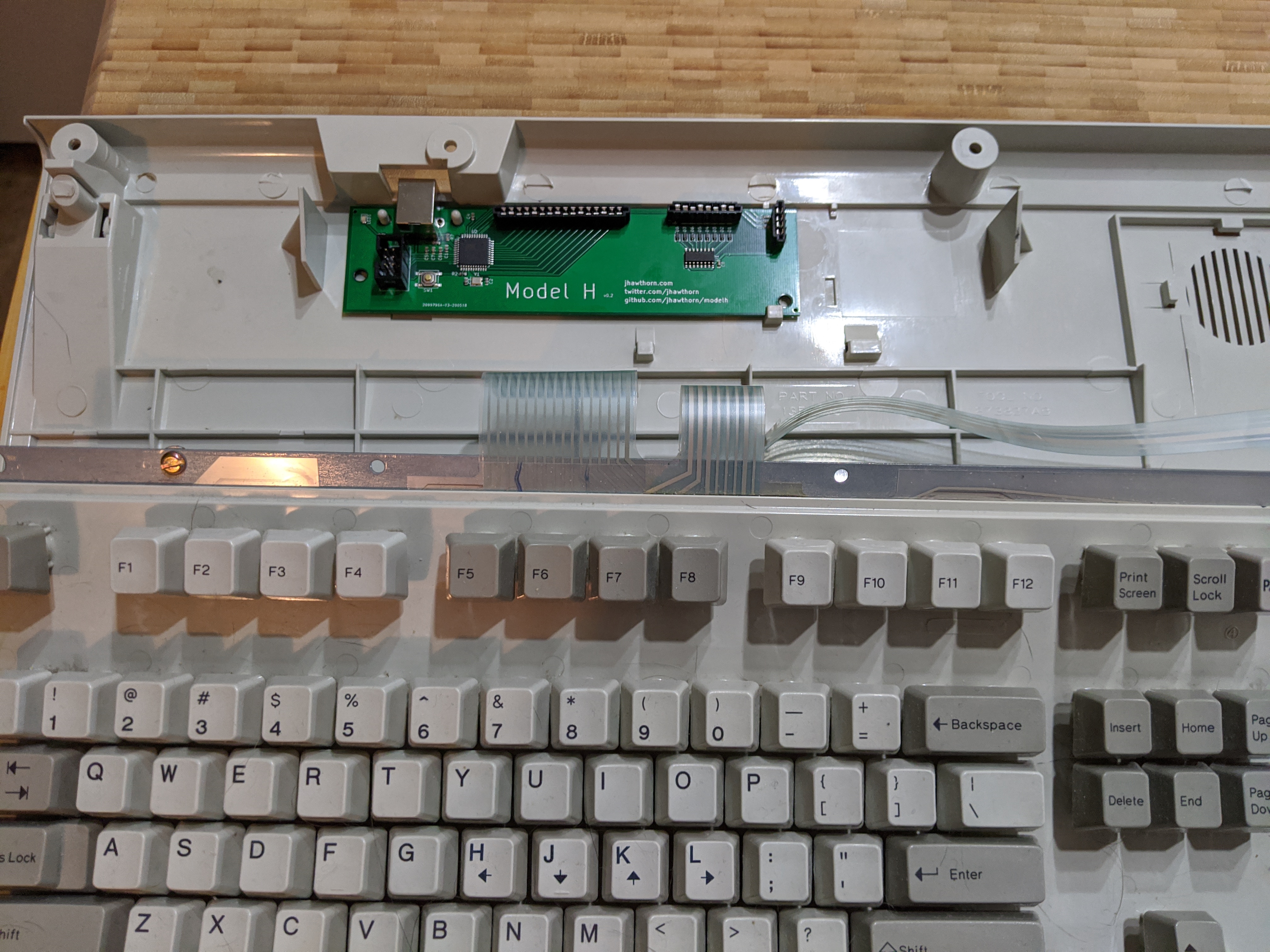
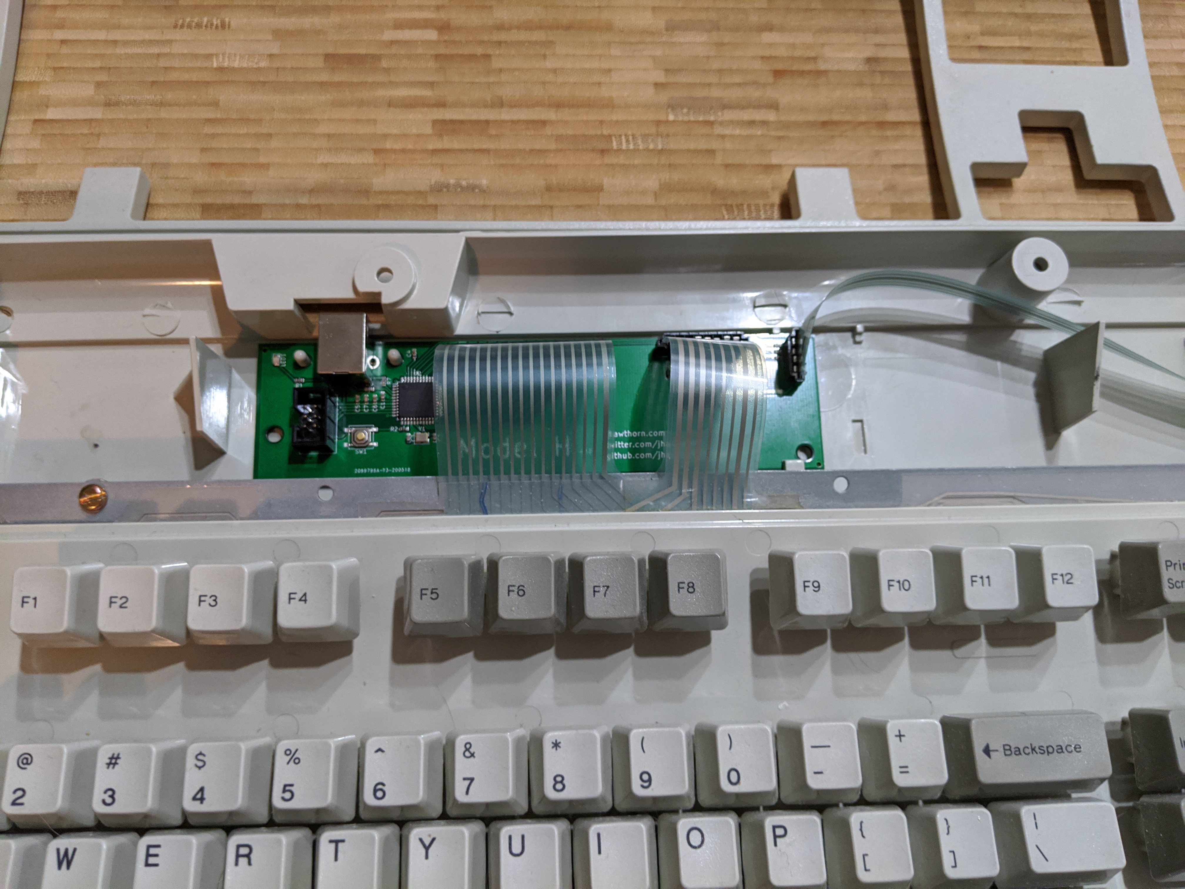
I’m integrating a new controller inside an existing design, so my first step was figuring out what parts of the keyboard are staying and what interface I’ll have available to work with. For the Model M this is the three flat flex ribbon connectors: a 16 position connector for “columns” (they don’t exactly represent columns and rows on this keyboard, but this is how I will refer to them), an 8 position connector for “rows”, and finally a 4 pin connector for the three LEDs on the right of the keyboard.
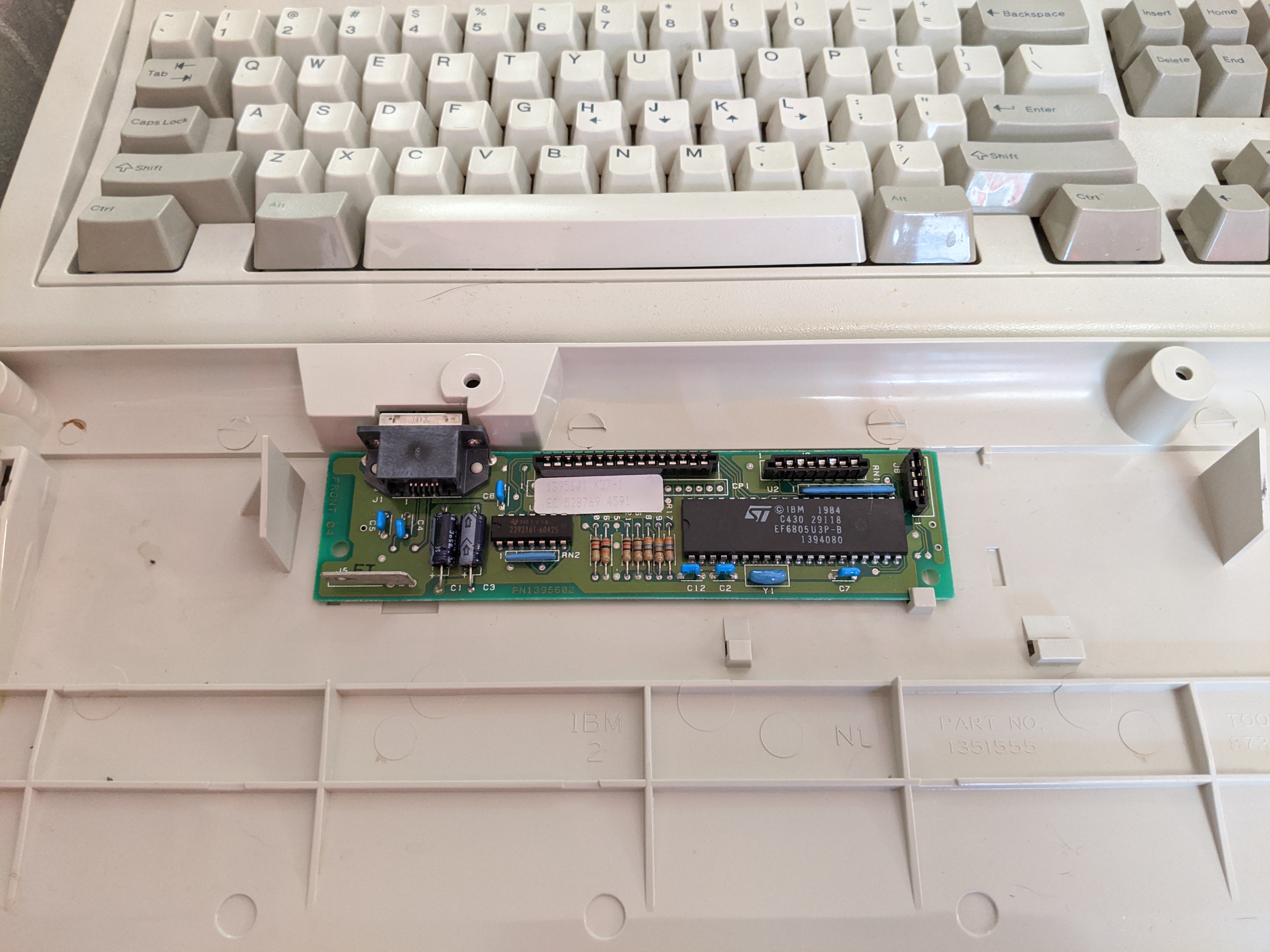
I found some posts about building a DIY controller which suggested salvaging the connectors from the original Model M controller, which I didn’t want to do. For starters, I hate desoldering. It also didn’t feel right to damage the original controller: this keyboard survived from the mid-80s and it seems a shame to make any permanent changes over 30 years later. I’d like this to be a fully non-destructive conversion. Finally if I only have one set of connectors I lose the ability to iterate on my design, which is important given that I, as usual, have no idea what I’m doing.
The required specifications for these connectors are for flat flexible connector with a 2.54mm (0.100”) pitch (spacing of electrical contacts), 0.13mm of flat flex thickness, and I needed one each of 16 contacts, 8 contacts, and 4 contacts. I plugged these values into DigiKey’s parametric search and it quickly filtered down to the 1-2 compatible products.
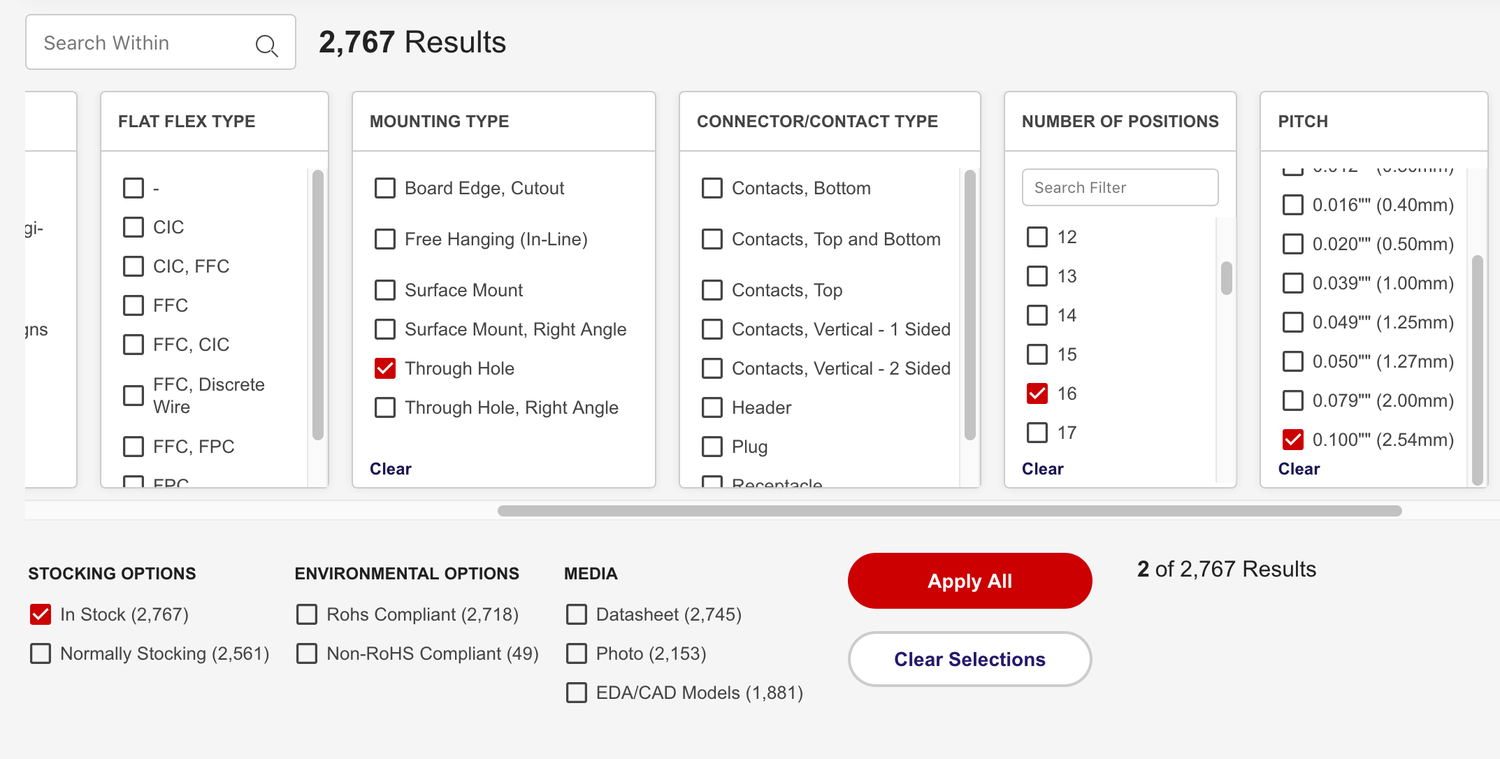
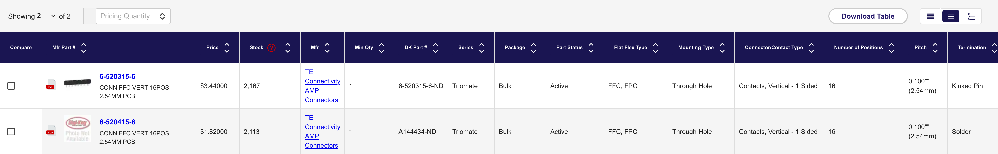
I ordered these from digikey and tested their fit on the flat flex cables before continuing. Luckily everything seemed to fit perfectly and they look nearly identical to the originals. After doing more research writing this, I think there’s a good chance that these are the same connectors that went on the original Model M controller. The manufacturer, TE Connectivity, has been in business since the 40s and the datasheet for these connectors have a copyright of 1981 (pdf link).
Version 0.1
Concept
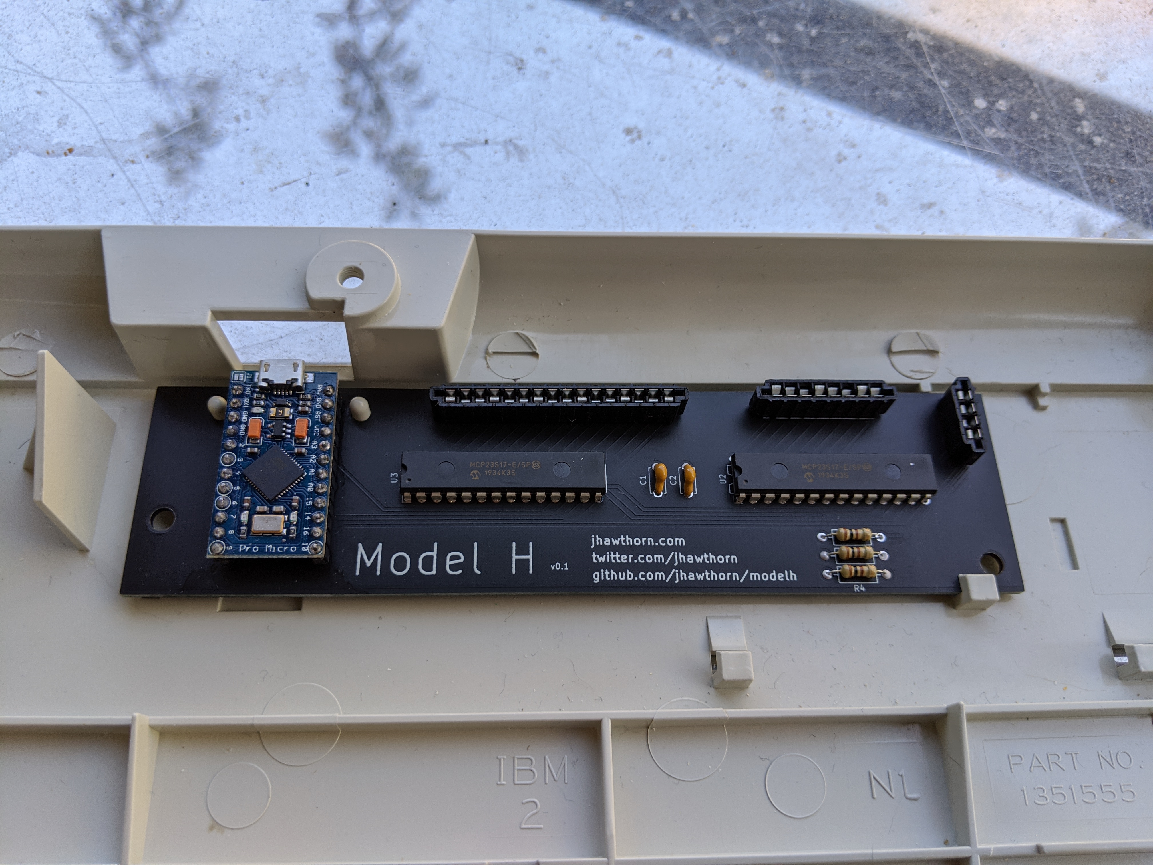
With connectors sorted, I went about designing the first version of this converter. For this I wanted to use an Arduino Pro Micro clone and a pair of I/O expander chips, MCP23S17, to interface with the keyboard matrix and LEDs. I wanted to use the pro micro because I’ve used them before, I had a few around, and they’re based on the Atmega32u4 which makes them suitable for use as a USB keyboard (the U is for USB). I/O expanders basically provide additional I/O pins by having the microcontroller talk to them (in this case over SPI) to configure whether the pins are read or write, what values they have, and pull up resistors. I needed the I/O expanders because I had 16+8+4 = 28 different electrical signals to manage on the outgoing ribbon cables, but only 16 pins from the Pro micro. I probably could have used just one I/O expander for 16 pins and the other 12 pins on the pro-micro, but I opted for two since programming both was about as easy as just one, and I wasn’t concerned about costs for this prototype.
It would have been a good idea here to use a solderless breadboard to test out and prototype before designing the PCB, but I had worked with these I/O expanders before, so knew how to connect them. Having full control of the outgoing pins thanks to the I/O expanders also made me confident this would work.
One thing I did need to get correct was the LEDs, since they needed to be configured with the right resistors and pinout to match the original controller. I spent some time checking continuity and resistor values on the original board to figure this out. I found that the 3rd pin was connected to +5V and the other pins were I/O pins (which are pulled low to turn the LEDs on) connected through 120Ω resistors.
Schematic
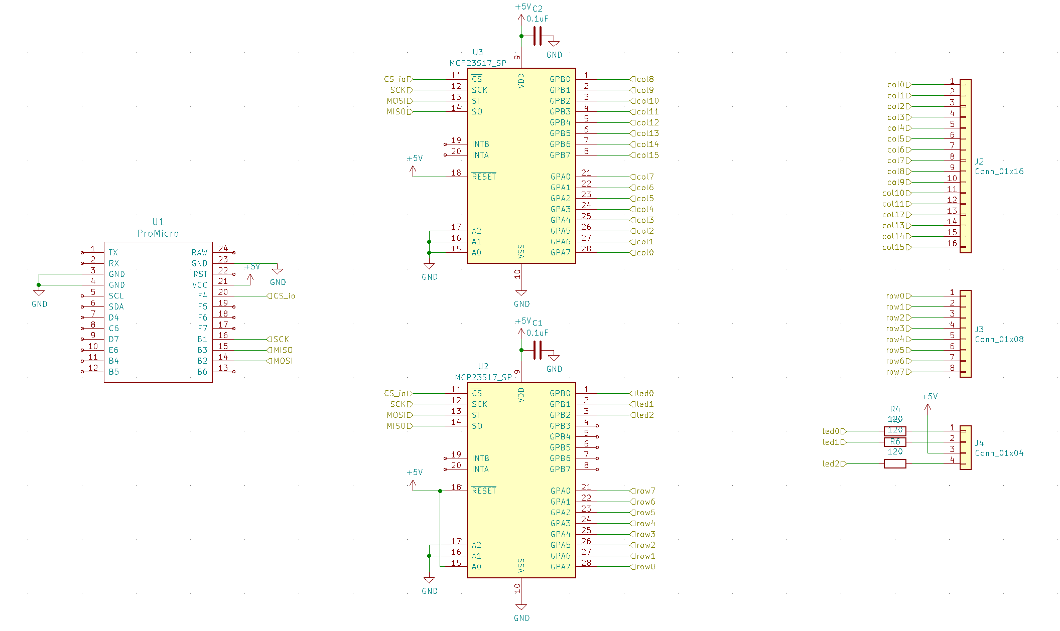
With this plan, I designed a schematic in KiCad. KiCad is a open source electronic design automation suite. Basically, it allows designing an electrical circuit and PCB layout which can be sent off to a manufacturer. The interface takes some time to get used to but thanks to some online tutorials after some time I was able to figure it out.
Thankfully, the schematic was fairly simple, I only have a few components and at this point I just need to declare what everything is connected to and resistor values. I also added some bypass capacitors for the I/O chips, which probably wasn’t necessary but couldn’t hurt.
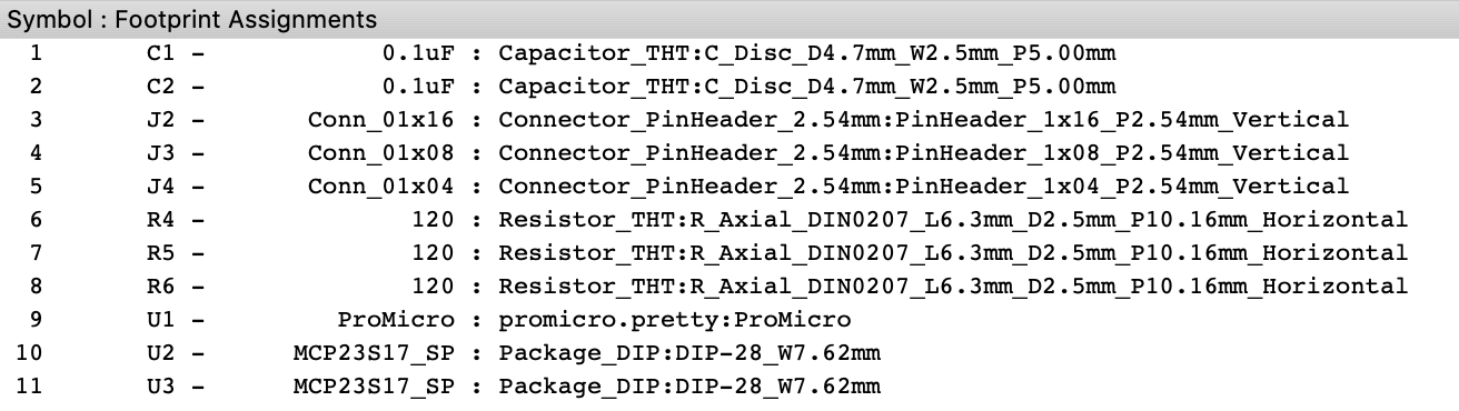
Footprints
After this the next step in KiCad is to assign footprints to each of these components. Footprints are designs for each component so that KiCad knows the physical dimensions and pinout of the components being used. I imported an external library, promicro.pretty, to provide the footprint for the Pro Micro board (otherwise I could have designed one myself). I used the 2.54mm vertical pin headers since i knew that was close enough to the flat flex connectors I was using. I used fairly generic footprints for the resistors and capacitors. Finally I used the generic DIP-28 package for the I/O expanders, which are DIP (dual inline pin) chips with 28 pins (as their product page confirms).
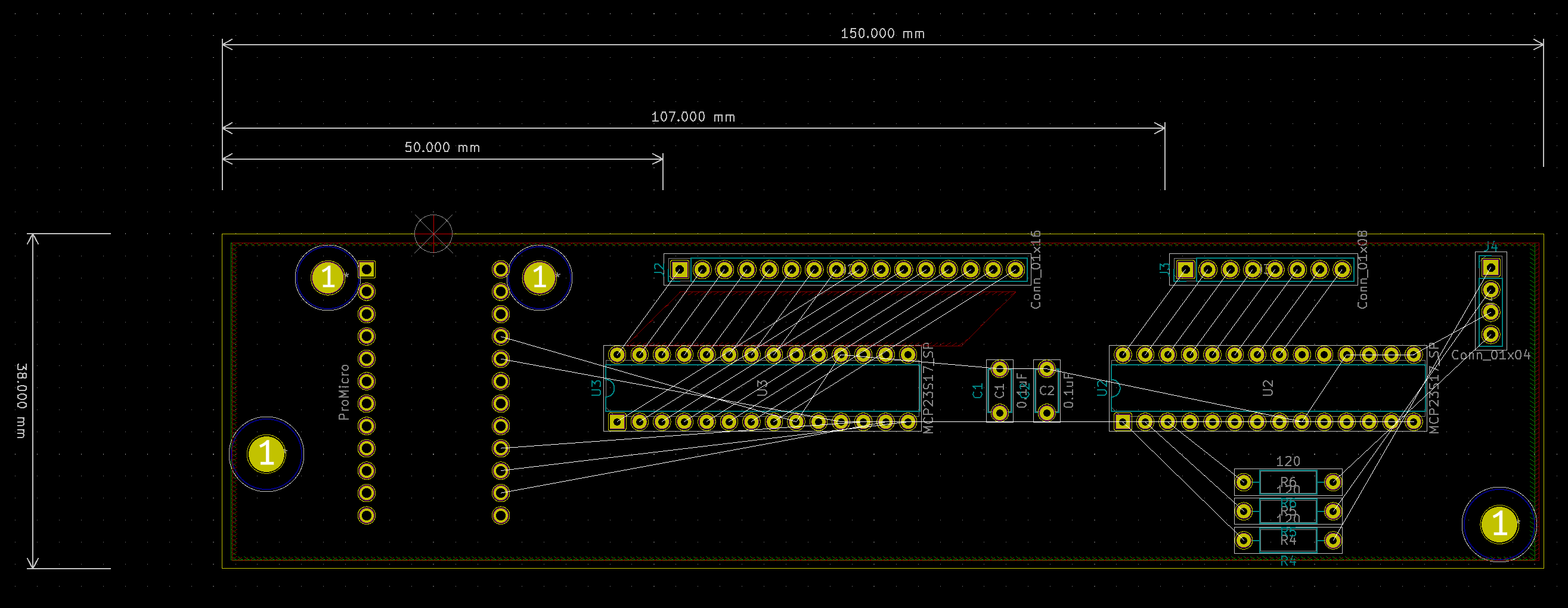
Layout
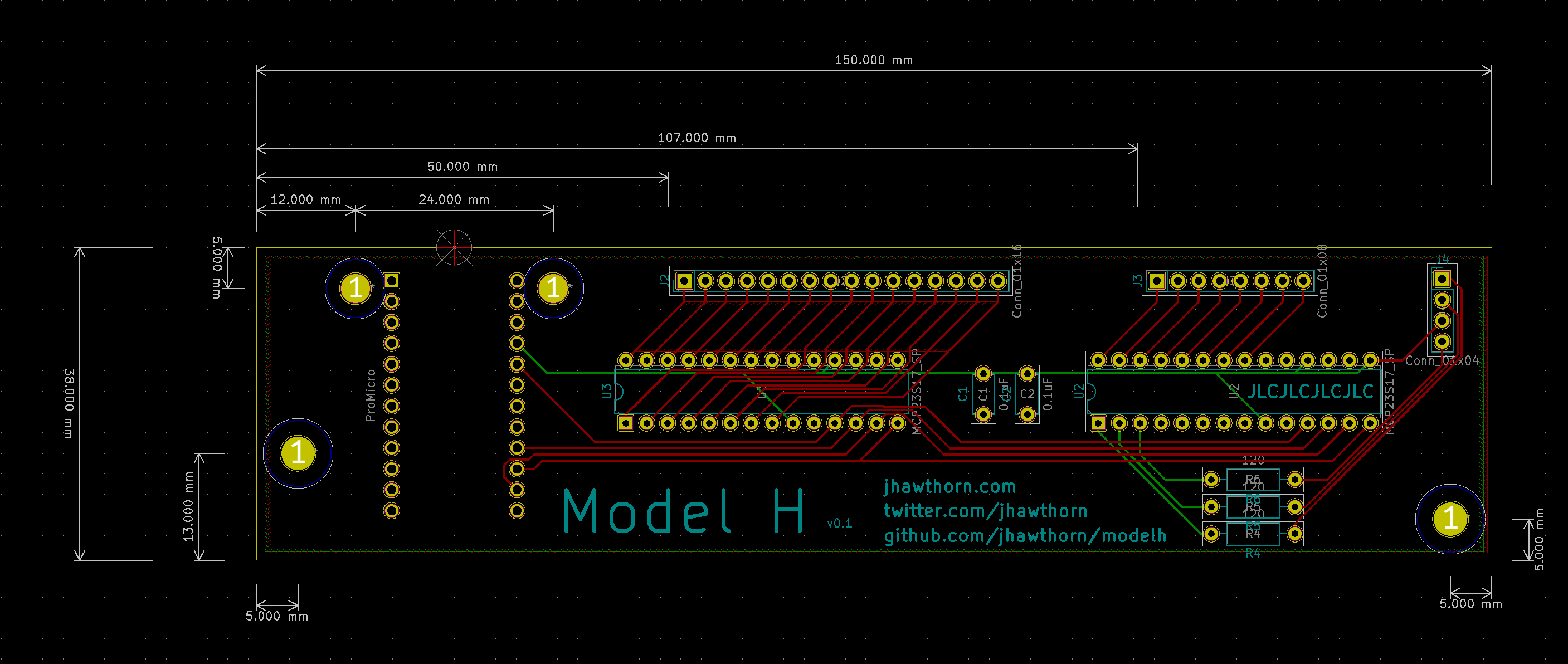
In this step I import the footprints from the previous step, and it shows how the components are to be connected. In this step some components needed to be in a specific place and the board needed to be a specific size and have specific holes to match the original PCB. I used a cheap set of digital calipers to measure as accurately as I could the size of the board (150mm x 38mm) size size of the mounting holes (3.5mm for the two next to the SDL port, 4mm for the other two), and the approximate positions of the flat flex connectors. I also knew where I wanted the pro micro. Then I places the I/O chips, resistors, and capacitors where I thought best made sense. I also drew a “cut layer” to denote the size of the PCB itself.
With this done, I now looked at the “ratsnest”, the lines between each pin of each component, and the nearest matching place they were supposed to be connected to. I then drew tracks connecting these pins. This was designed as a two-layer board, front and back, so tracks can go on either side, and from one side to the other using a via. It feels like a bit of a puzzle and a bit of an art to making this layout. I just try to keep the tracks as short and neat as possible. I ended up changing the order of some of the pins in the schematic to make this simpler and cleaner, since I knew I could fix this in software.
With the PCB design done I ran the “design rules check”, and fixed any problems it reported.
Manufacture
Finally, with the PCB layout done, I was able to send this to manufacture. I used jlcpcb, who were the cheapest for PCB prototypes that I could find at this size and volume (and the cost was mostly in shipping). It’s good to, once you know the dimensions of your board, check a few manufacturers order/quote pages, and play with the various options.
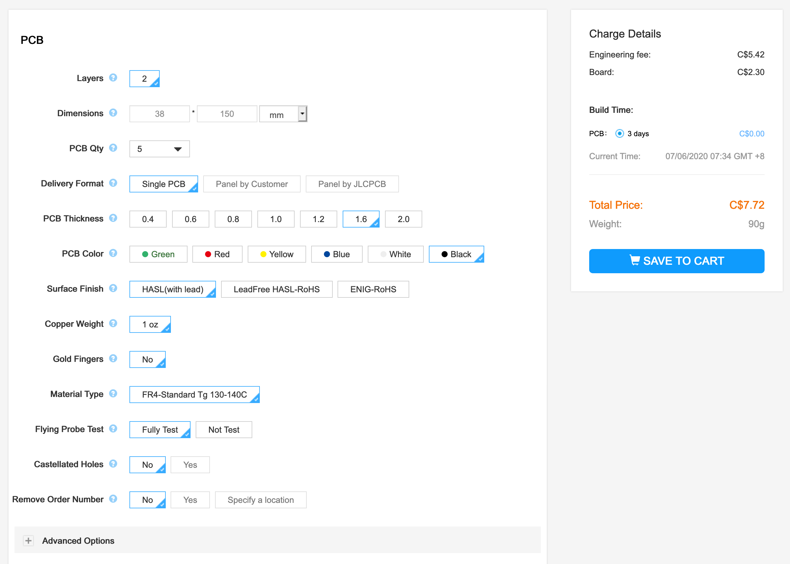
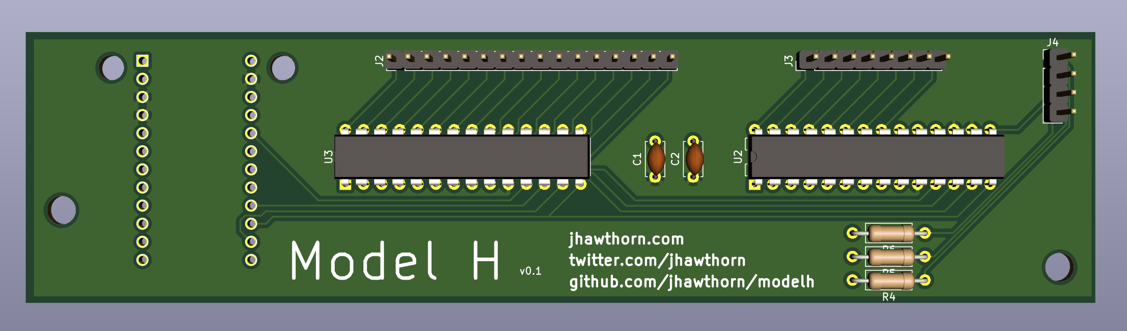
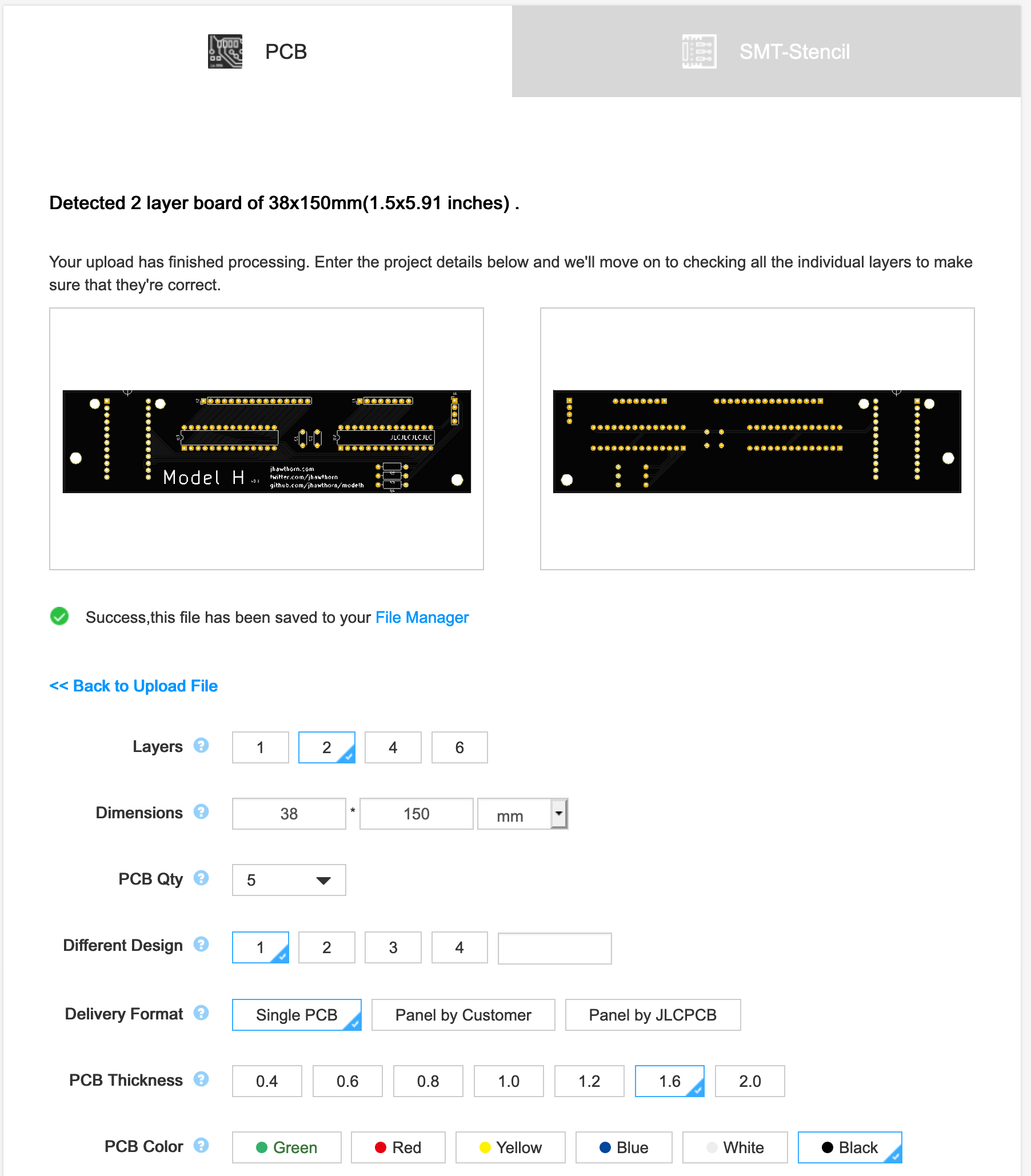
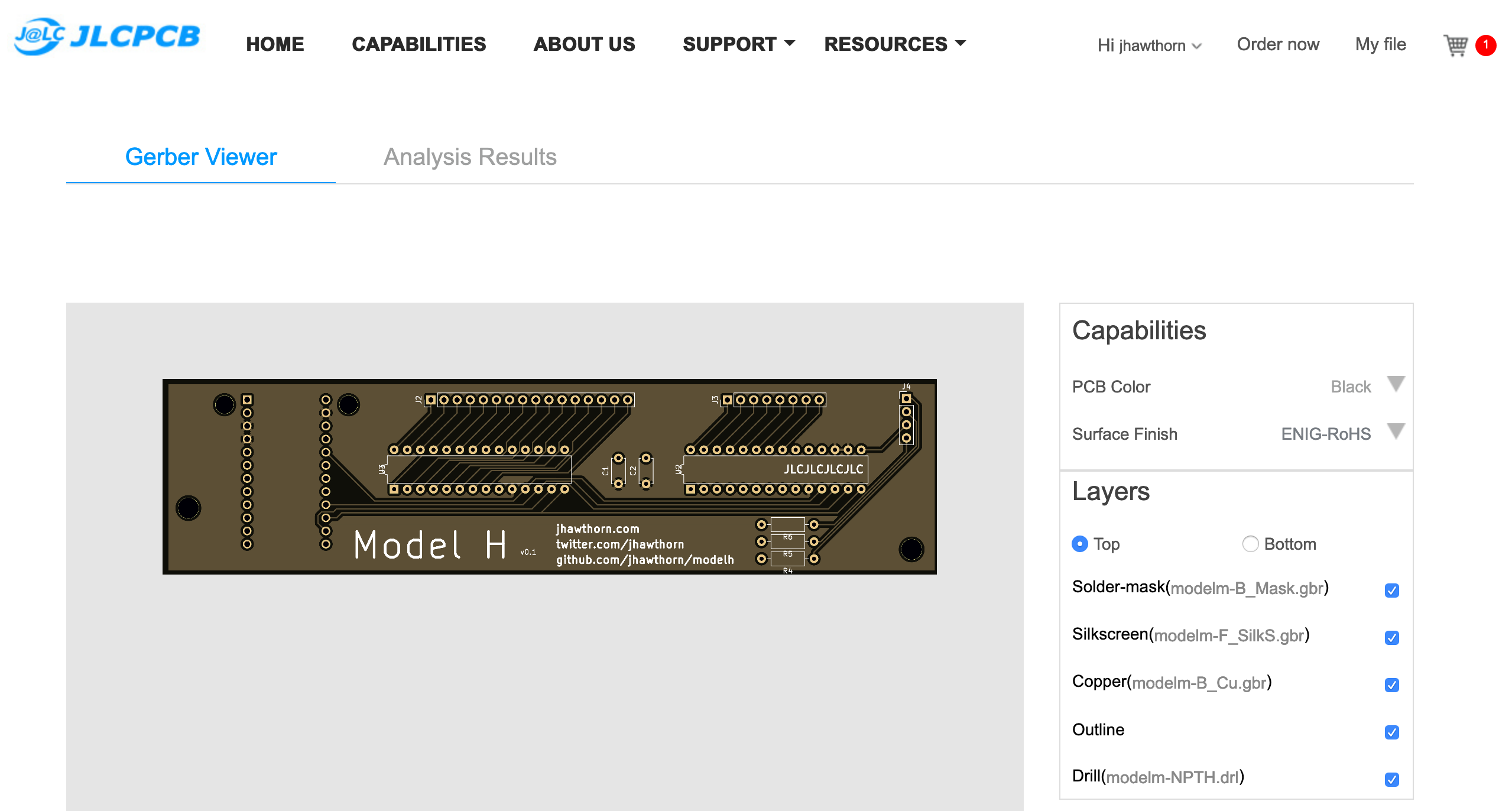
Most manufacturers will want “gerber” files, which can be generated from “File -> Plot” in KiCad’s Pcbnew. On uploading these, most manufacturer’s websites will provide a gerber viewer which can help provide a quick visual inspection that things are going correctly.
I was able to order these PCBs for about $50CAD, of which almost $39 was shipping (they recommended against their cheaper options due to COVID-19). A few weeks later, it arrived!
Software
One of the reasons I wanted to make a custom controller is to be able to use a firmware like QMK. I’ve been spoiled by this on my Ergodox and the ability to remap keys and have multiple layers is now practically a must have for me.
Most keyboards work by “scanning”/”polling” a matrix: sending an electrical signal and seeing which columns the signal appears on. Each blip on my oscilloscope here shows my keyboard checking row 0 one time.

We bring each row pin low (or ground or 0) to scan for the columns on that row. Low is used because the inputs have pull-up resistors which makes it possible to check vs having no electrical signal at all. For the pins of rows we aren’t scanning, we set those pins as inputs, so that they don’t have any output at all (they are “high impedance”).
One thing I found notably missing from this design was a reset button. I had to short the RST pin on the Pro Micro to ground every time I wanted to upload more code. Once the keyboard started working though, I was able to use QMK’s “magic” shortcut to upload code: hold down both right and left shift and press B.
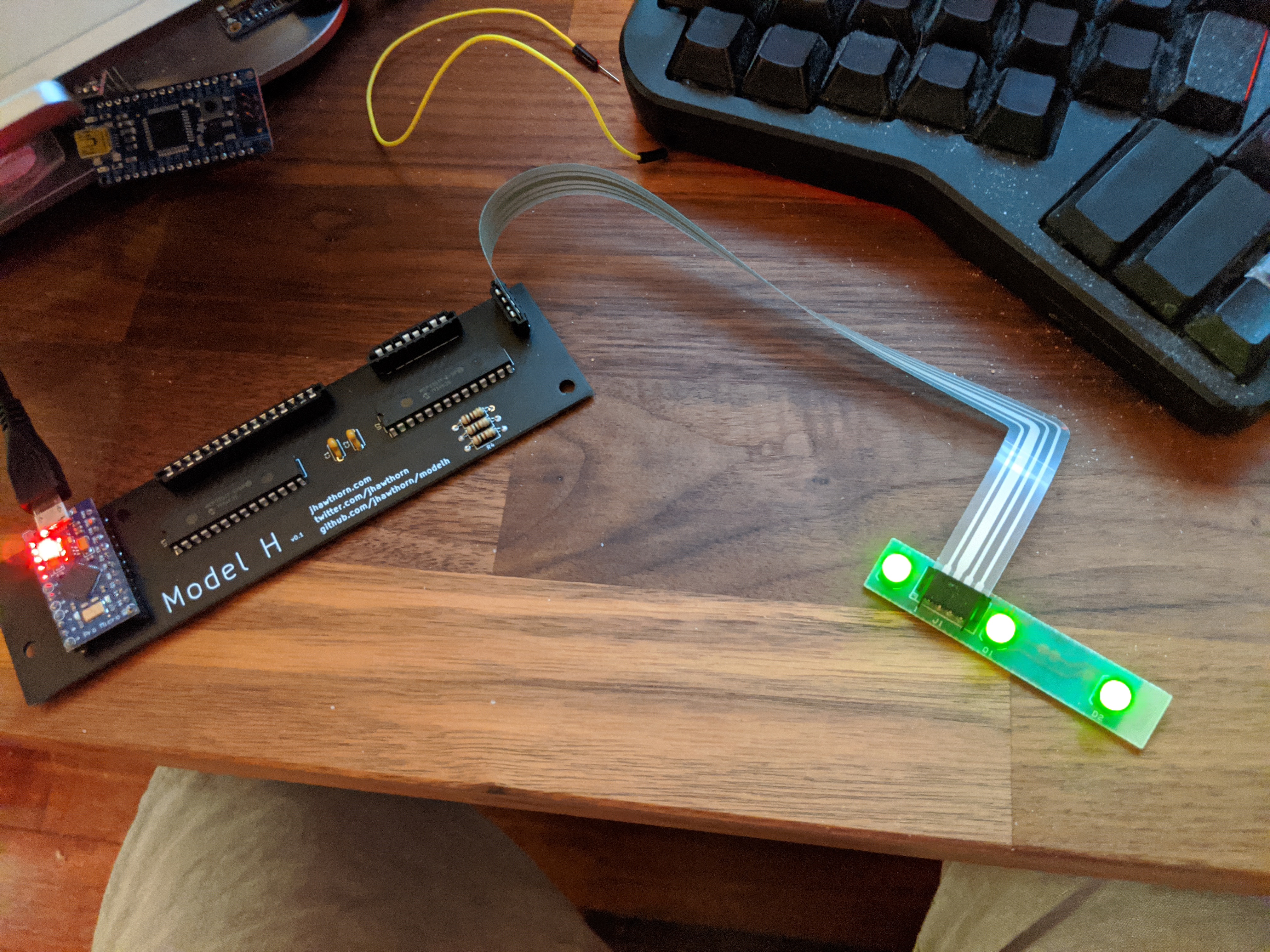
The full code for this version of the matrix scanning can be found on my GitHub.
Version 0.2
The first prototype completely worked (to my surprise), but it left me wanting to design a cleaner, improved version. I didn’t love using the Pro Micro as a daughter-board and the micro-usb didn’t quite match the feel of the 2kg Model M keyboard.
I also spotted that jlcpcb offered SMD assembly and was interested in exploring that. I’ve always shied away from doing any SMD work by hand, my soldering is just a little bit too clumsy for it. It should be possible if I tried harder and invested in solder paste and a heat gun, but paying for machine assembly makes that all unnecessary and stress-free.
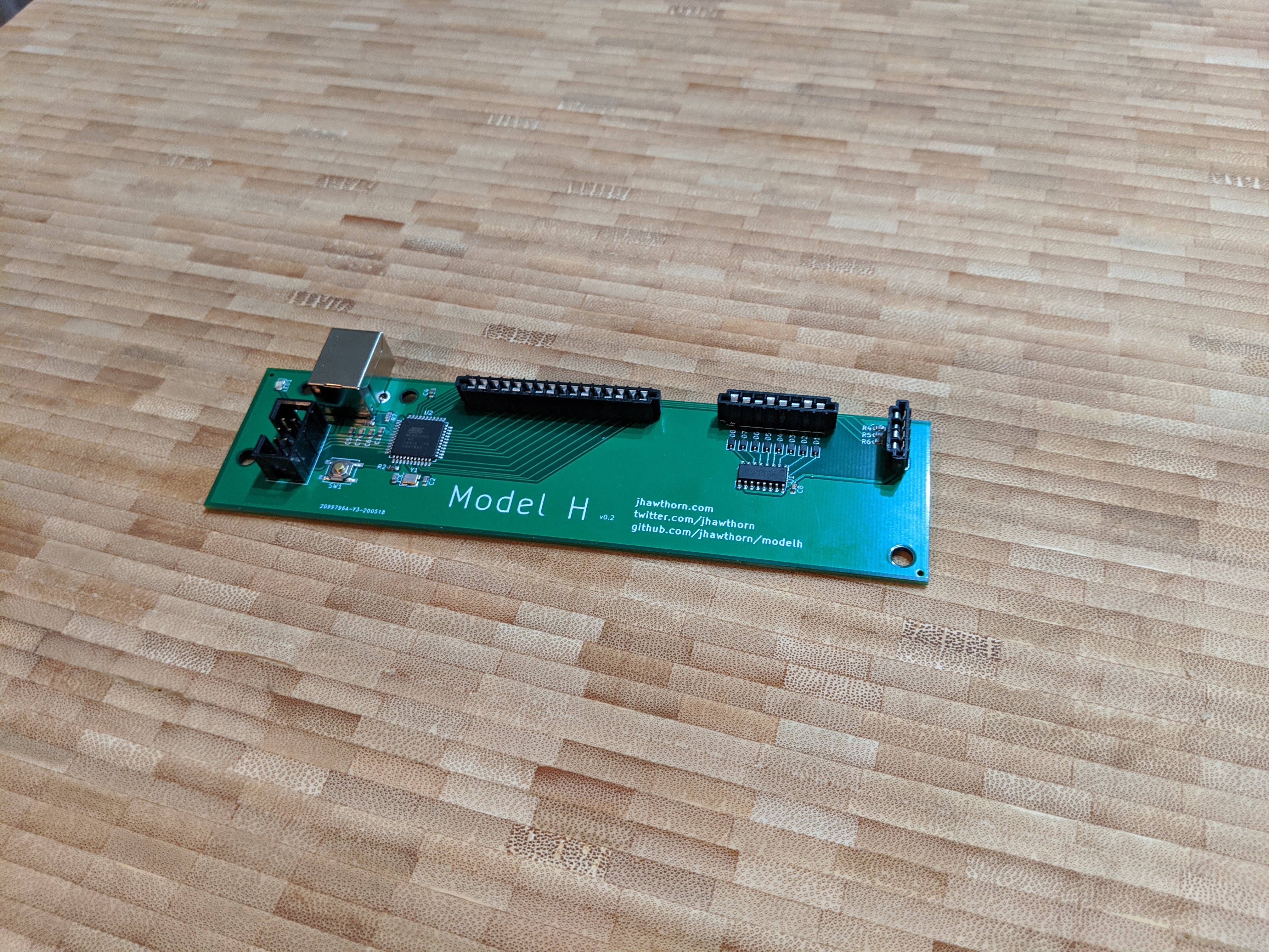
So I set out to make a second prototype with everything on a single board, using SMD components, and having assembly done.
Components
Deciding to make an SMD version changes what components are available. A lot of components are only available by SMD. This gives us access to microcontrollers like the Atmega32u4 directly instead of just breakout boards like the Pro Micro. However, since I want jlcpcb to assembly the board for me, I’m limited to the parts they have in stock. Fortunately, they have a huge library (they claim 30 000 components).
Some parts will still need to be through hole, specifically the flat flex connectors, and USB B connector. I’ll still need to solder these myself at home. However I wanted everything else to be SMD.
An additional complexity is that jlcpcb categorizes their components into “basic parts” and “extended parts”, which cost an extra $2 and they allow a limited number of them. So as much as possible we are going to try to use basic parts.
So even though the MCP23S17 is available through jlcpcb, and I could use the same design, I’m going to try to avoid using them in this more finished project. Ideally I’d be able to put all the I/O on the main microcontroller.
There are more pins available now on the microcontroller, the Pro Micro doesn’t expose all of them, but there still aren’t enough to manage all the signals from the keyboard matrix. In an ideal world I could use a microcontroller with more available pins, like the At90usb series which the Teensy++ uses, but those aren’t currently in stock at jlcpcb. I have enough pins available for the 16 pin header, and for the three LEDs, but that leaves me with with only 6 pins remaining, and I need 8, and some of those 6 I’d rather not use since they have alternative uses like SPI and in circuit programming.
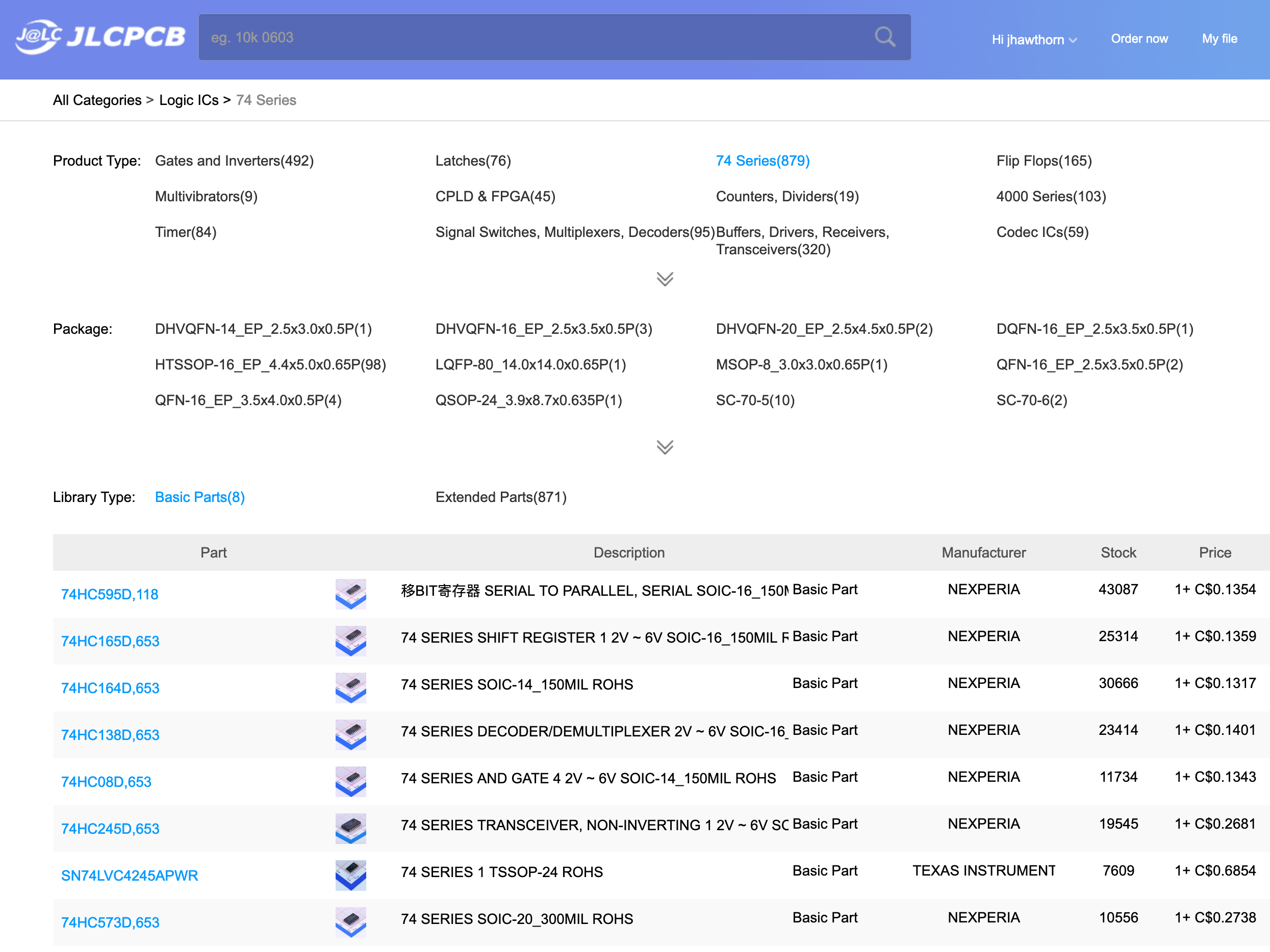
What I decided to use is a 74HC595 shift register chip. The 74xx series of chips are classic, widely available logic chips which are made by a lot of different manufacturers. The 74x595 allows us to shift serial data in using three microcontroller pins to eventually control 8 outputs. Best of all, this version of the 74x595 is a basic part.
This works because in the previous prototype that the 8 pin connector (which I’ve been calling rows) is an output and I never need to read from it. However it’s not quite a standard output, otherwise each keypress would short two rows together, I actually want each pin to either be pulled low (0v) or to have no output (also called high impedance, hi-Z, or floating) which isn’t the same as 0. In the previous version this was done by setting the pins to read, so they weren’t outputting but in this version since I know I only ever want low (0) or hi-Z I can achieve this with a diode on each output.
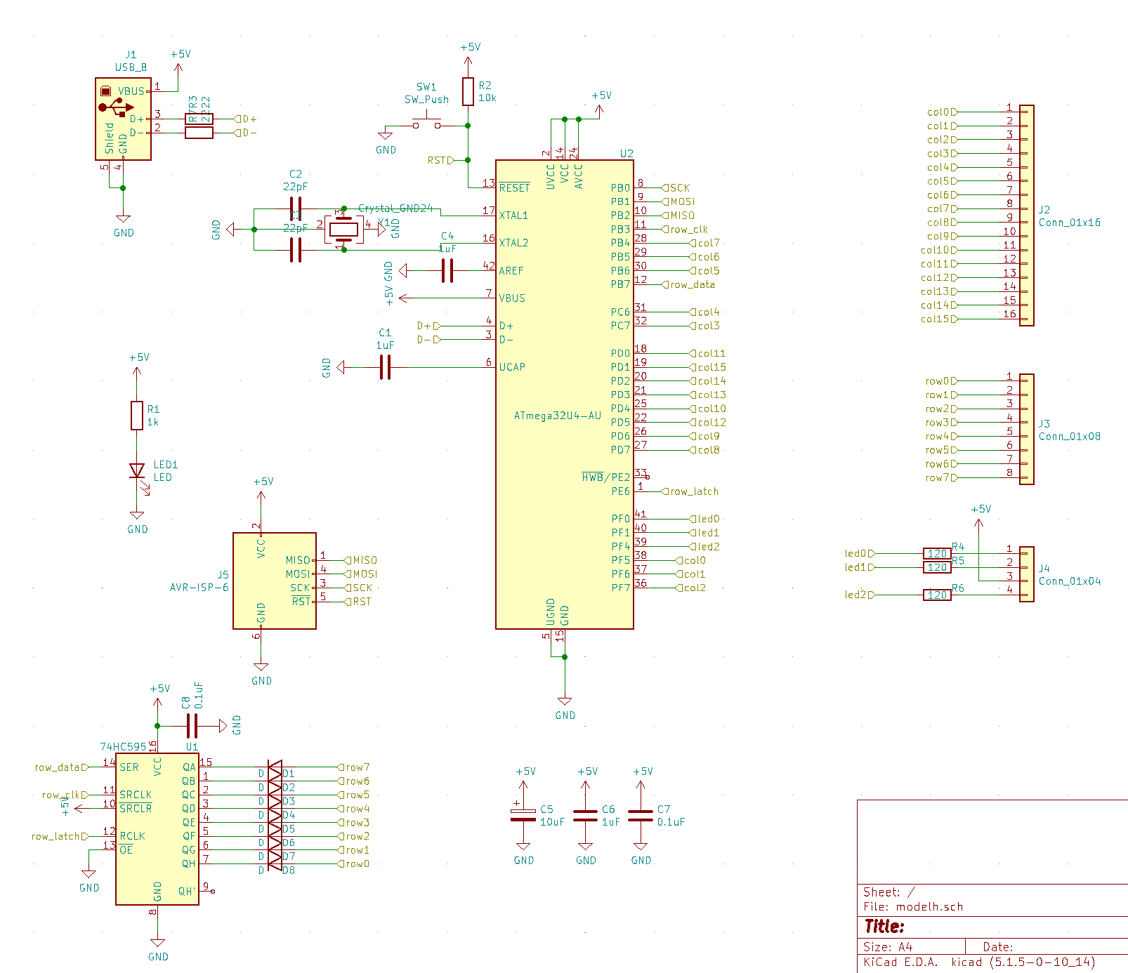
Schematic
Now that I’m using the Atmega32u4 directly there’s a few more components needed. I now need to replicate a lot of the support components which were previously where already on the Pro Micro board. In addition to the rather long 32u4 datasheet, I found referencing the schematic for the Adafruit Atmega32u4 really helpful (Adafruit is the best!). For support microcontroller needed a 16MHz crystal, some capacitors, and a pull up resistor.
I also added a power LED and reset button. It’s important that the reset pin on the microcontroller has an external pull up resistor.
Another change is adding the AVR-ISP header, which allows both programming and debugging of the microcontroller. This was possible to use since we didn’t dedicate those pins to other purposes.
Footprints and part numbers
Footprints were similar to last time. It was important to be careful to choose the right footprints, since practically everything on this board from the Atmega32u4 to each resistor and capacitor can come in different footprints, and they needed to match exactly the part I was ordering (and that part needed to be available).
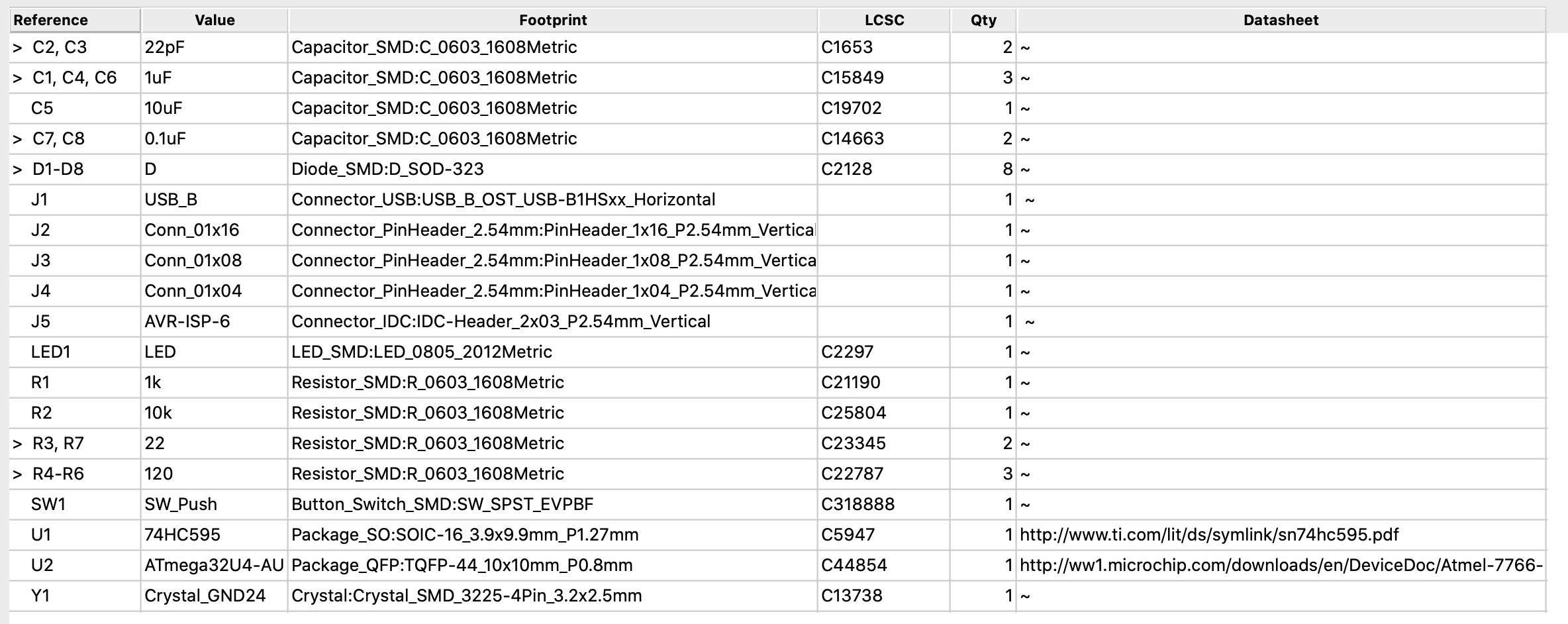
In addition to setting the footprint I needed to add the LCSC (jlcpcb’s components store/warehouse) part number for each component, so that I could eventually generate a “pick and place” file to send to jlcpcb. I did this for each SMD part in the “Edit symbol fields” modal of KiCad’s Eeschema.
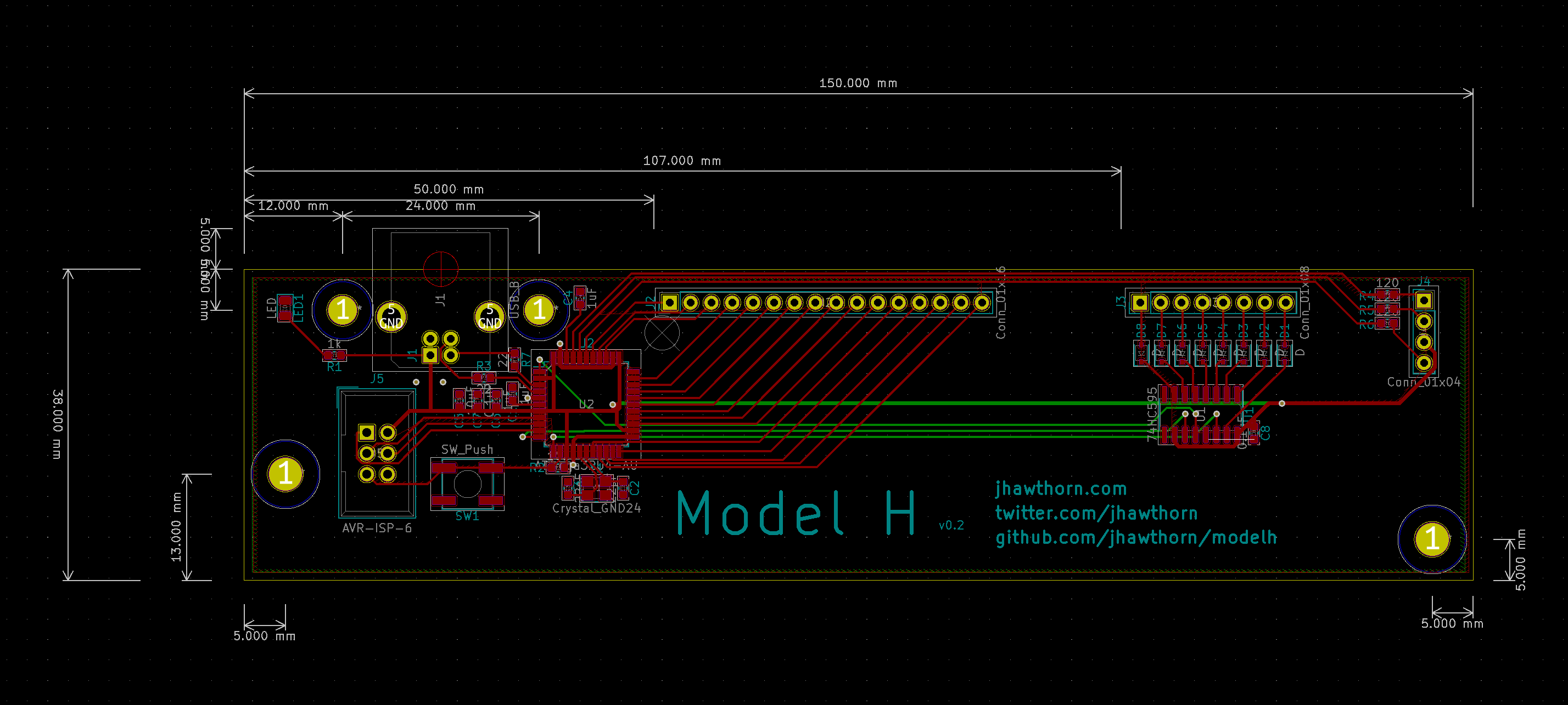
Layout
I was able to copy and reuse the basic dimensions of the existing layout. There were more parts and therefore more traces to route this time. The parts were also smaller which was both helpful, since it was very easy to fit everything, and unhelpful, since it was harder to route around components. Even more so than in the v0.1 layout I swapped pins around on the microcontroller to make routing simpler.
Eventually I was able to get a layout I was quite happy with.
Manufacture
I generated and sent the gerber files exactly as before, and selected options mostly the same as before (though unfortunately they only do assembly on green PCBs). This time selecting the option for PCB assembly.
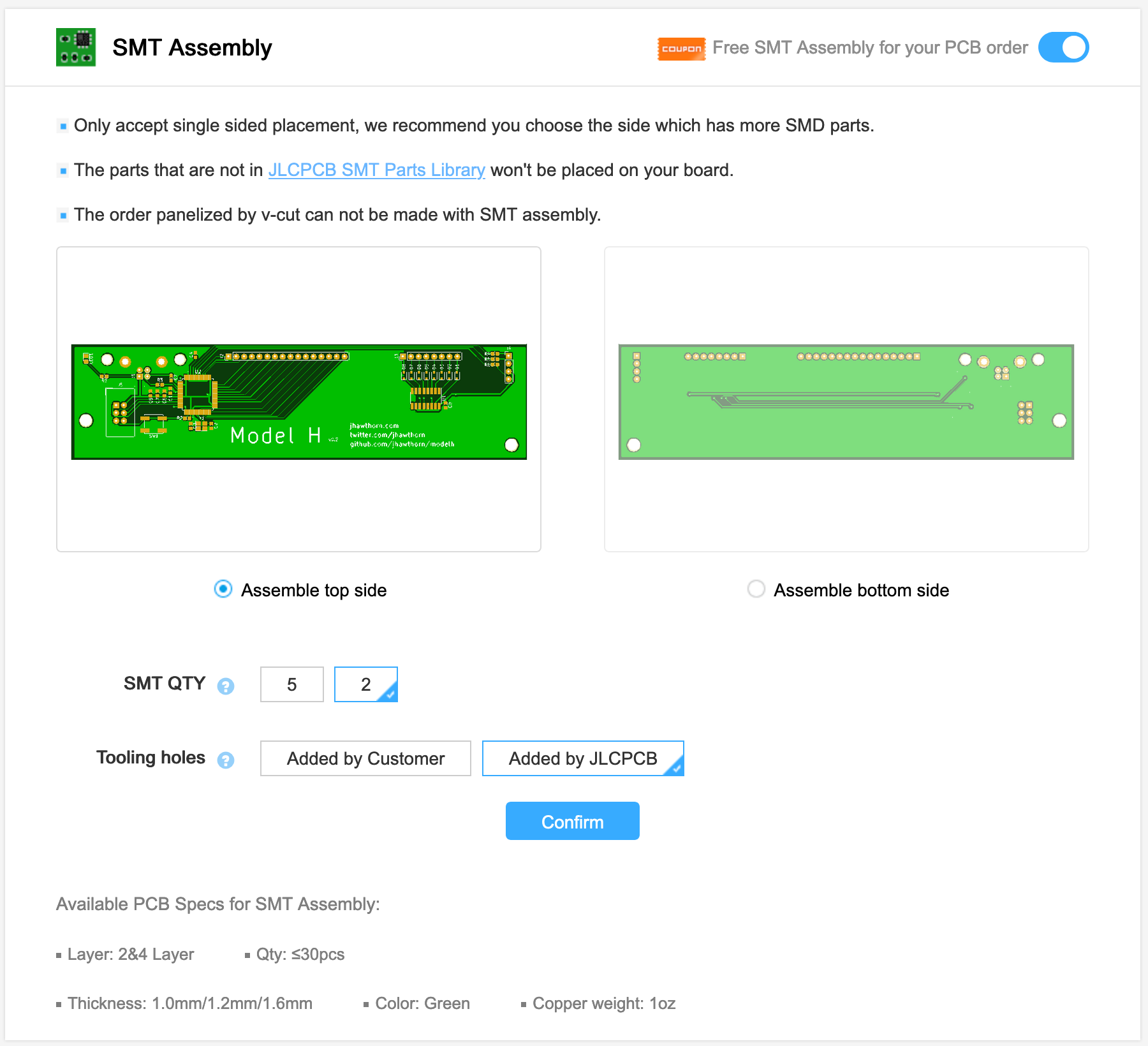
Having assembly done requires generating two extra files: one BOM (bill of materials) file which lists all the components and a second “pick and place” (named after the machine which picks and places the components on the board to be soldered) file. They have a help article I followed pretty closely.
For some reason the pick and place file had the wrong orientation for a few of the components. I’m not sure why this was; I could have done something wrong or possibly KiCad disagrees with jlcpcb on the “default” orientation of some of these parts. In any case I was able to fix this by editing the “pick and place” CSV file by hand and rotating components into the right position.
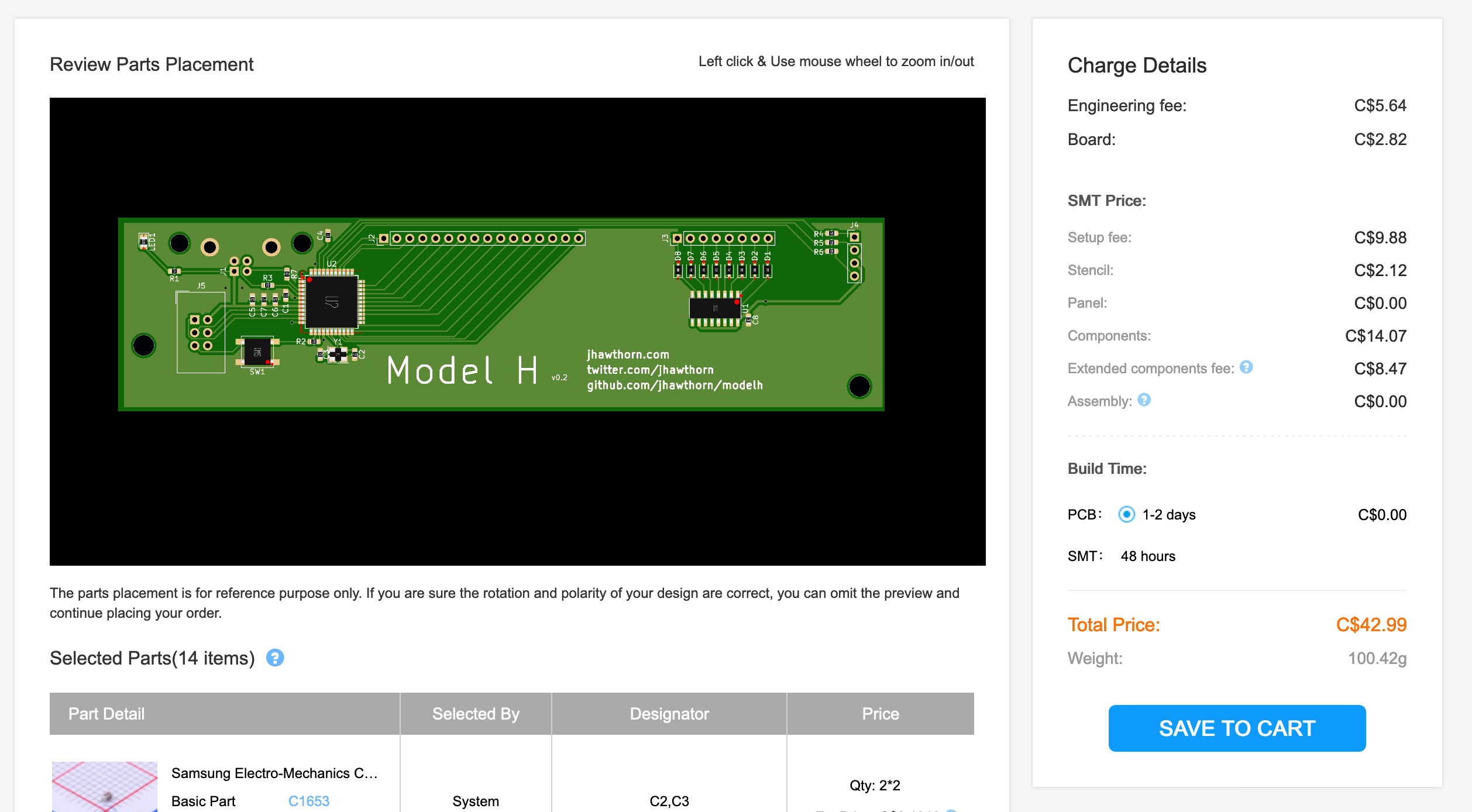
With everything seemingly in it’s right orientation I placed the order. This time I chose a cheaper shipping option this time, so the order breakdown for two assembled PCBs was: $8CAD PCB, $33CAD SMT assembly, $15CAD shipping.
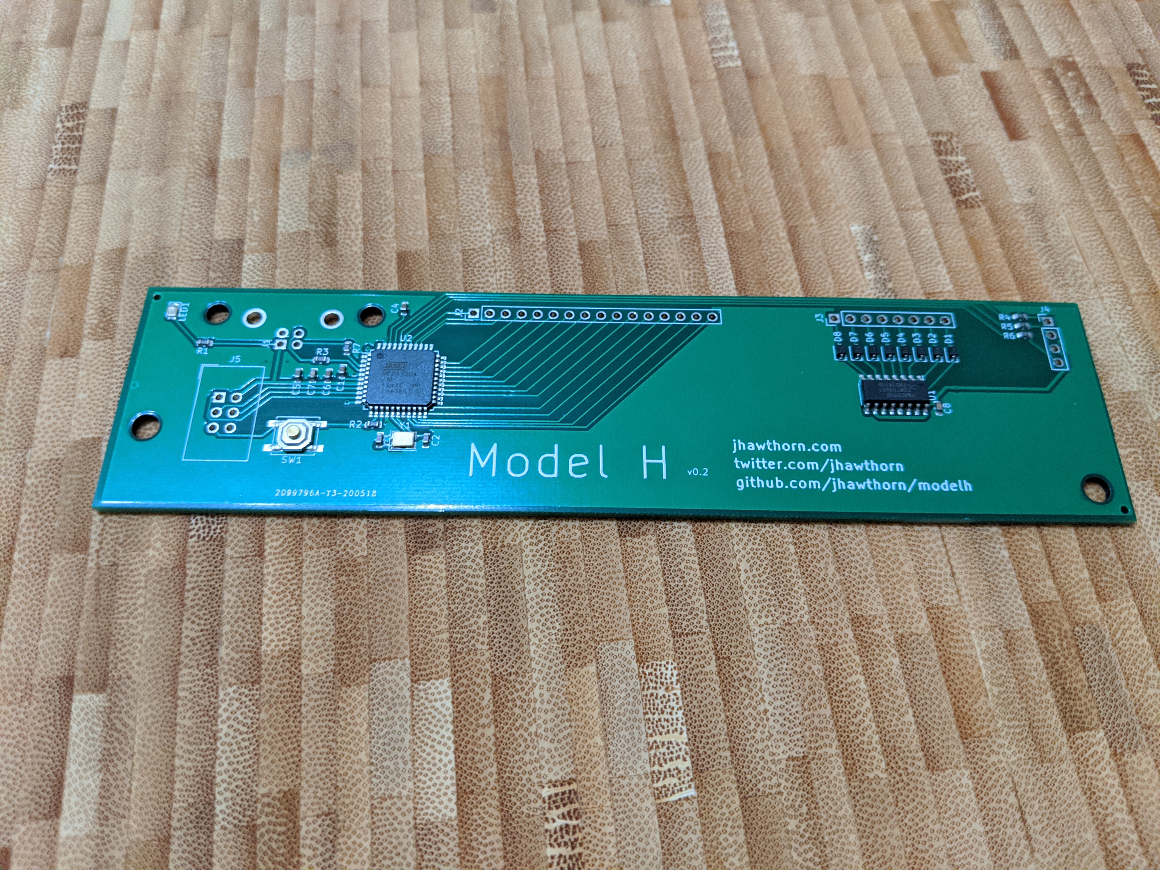
About a month later I had my working, assembled PCB arrive at my door.
Software
I was thrilled to find that the Atmega32u4 came with a USB bootloader included, so I didn’t end up needing the ISP immediately (though I’m glad to have included it). The reset button was also a welcome addition to this version over manually shorting the reset pin to ground on v0.1.
From the previous version of the software I mostly just removed the SPI code for the I/O expanders, or replaced it with code to control the shift register. I also needed to do some extra work because the pins were in a more arbitrary order than before in order to simplify the PCB layout, but QMK was already well designed to support that.
What’s next?
What I’ve built works perfectly for my Model M, but there are other models out there, as well as the similar Model F keyboard.
I tried as much as possible to replicate the size and holes of the original controller is in hopes of being compatible with as many versions of the Model M keyboard as possible, but I can’t know until it’s actually tested. I know that some versions also don’t use a flat flex connector for the LED strip, and I’d like to figure out how to support that.
I’m also interested in switching to an STM32 Arm processor, which are inexpensive and a few of which are basic parts on jlcpcb. I might even be able to find one with enough pins to avoid the 74HC595.
I’d like to replace the three green status LEDs with modern RGB LEDs. LED technology has come a long way since the 80s and 90s in terms of brightness/power and it would be nice to have some outside indication of how cool this modded keyboard is.
I’d also be interested in further productising this. If there was enough interest I’d like to make a batch of maybe 100 of these controllers and figure out logistics for selling and shipping them. I would probably need to find a different place to assemble the PCB, as JLCPCB only does small quantity assembly. This would have to happen after I had a better idea of compatibility.
If you have a Model M and are interested or could help me figure out compatibility please get in touch with me @jhawthorn on Twitter or john@hawthorn.email.
Thanks
Aaron Patterson for encouragement and advice on SMD assembly.
Benjamin Willems for encouragement and buying me a part from DigiKey.